
Daggerboard Detector
The Daggerboard Detector is a completely non-intrusive system that uses radio frequency techniques to “see” daggerboard position. It is not dependent on magnetic or optical techniques and requires no string pots or other mechanical connections to the boards.
Using RFID tags embedded in your daggerboards, the system is capable or reading board position through as much as 100mm of carbon, foam, air and water. From these tags, it generates board position information suitable for display on cockpit instrumentation systems and/or logging.
The system also generates a signal indicating whether the board’s position is “safe” or “dangerous”. This signal can be interfaced to a canting keel controller to prevent moving the keel when doing so might cause the keel bulb to hit a daggerboard. This helps to prevent canting mechanism damage, board breakage and dings to the bulb that increase drag and reduce speed. Be sure to check the downloads page for more information
System Components
The system is comprised of three components: the tags, an antenna mounted on the trunk and a reader module. One reader/antenna pair is required for each daggerboard trunk. A standard system is comprised of two reader/antenna pairs and 100 tags, usually enough to instrument two boards of up to 5 meters in length. Also included are all necessary connectors and a USB adaptor cable used for “learning”. All you add is power/interface cabling and mounting hardware.
About the tags

The heart of the system is the tiny indicator tags buried in the lay up of the boards. The tags are approximately 24mm in length and 4mm in diameter and can be held in place by structural foam or epoxied into honeycomb or other internal structure of the daggerboard and covered with fiberglass, Kevlar or carbon skins.
While the tags are most easily installed as boards are built, they can be retrofitted into existing boards by drilling and gluing the tags in place with epoxy filler. We recommend a pitch of 100mm. The tags are waterproof and shockproof and can withstand temperatures of up to 125° C for 100 hours – more than enough to tolerate post curing.
While the tags are most easily installed as boards are built, they can be retrofitted into existing boards by drilling and gluing the tags in place with epoxy filler. We recommend a pitch of 100mm. The tags are waterproof and shockproof and can withstand temperatures of up to 125° C for 100 hours – more than enough to tolerate post curing.
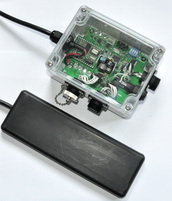
About the Antenna
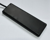
The antenna, measuring about 170 x 65mm and less than 10mm in thickness, can read tags from a distance of about 100mm through carbon, foam, water and air.
In most installations, the antenna is mounted inside the boat, adhered to the trunk skin, no thru-holes are necessary.
In most installations, the antenna is mounted inside the boat, adhered to the trunk skin, no thru-holes are necessary.
About the reader
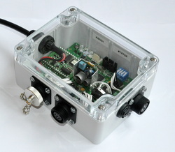
The microprocessor-based reader is responsible for real-time detection. It generates two different outputs.
The first interface is via NMEA® 0183 and reports board position as a percentage of maximum depth. The information in the NMEA sentence can easily be logged with a variety of on-board navigation software. It can also be displayed by integrated electronics systems. We've worked with B&G, NKE and Cosworth and can work with other suppliers on your behalf.
The second interface is an open-collector alarm signal that indicates whether the board position is safe or dangerous. This is intended for use as an interlock with the boat’s keel controller. The Kinetic Scientific Keel Controller has built-in support for this interface. We've also provided custom support for various 3rd party controllers.
Learning daggerboard profiles
Because the geometry of each boat is unique, the specifics of a board, its tags and the trunk cannot be known in advance. Instead, the system is “learns” about each board/trunk combination during the commissioning process. Full support is included for port, starboard and reversible boards.
To accomplish this, each board is positioned in its trunk, and, while running the supplied PC-based software and following some simple steps, the system is taught the board’s geometry in about five minutes. Once the learning process is complete, the board’s profile data is stored in non-volatile memory on the reader and also within a file on the PC. Up to five such profiles can be stored in each Reader at one time so no downtime is required when swapping out a damaged board. The PC is only used during this learning process and is not necessary for normal operation.
To accomplish this, each board is positioned in its trunk, and, while running the supplied PC-based software and following some simple steps, the system is taught the board’s geometry in about five minutes. Once the learning process is complete, the board’s profile data is stored in non-volatile memory on the reader and also within a file on the PC. Up to five such profiles can be stored in each Reader at one time so no downtime is required when swapping out a damaged board. The PC is only used during this learning process and is not necessary for normal operation.
Specifications*
|
Supply Voltage:
Power Dissipation: Data Interface: Canting Interface: Tags: Weight: Environmental Protection: Thermal limits: |
8-50 VDC
Less than 2W per reader EIA-422-A/NMEA 0183 Voutput high: 30 V Max Ioutput low: 1 Amp Max 24 x 4 mm Recommended pitch: 100mm Reader & Antenna: 350g Tags: 0.6g each
|
* Specifications subject to change without notice.
NMEA is a registered trademark of the National Marine Electronics Association
NMEA is a registered trademark of the National Marine Electronics Association